Monday, 24 February 2025

Governor Body

 Lack of blog entries are a measure of personal lethargy, rather than lack of progress, as followers of the Facebook page will know there’s lots of riveting stuff going on, but let’s get some of the blog backlog out of the way first. 

The previous blog entry described the high-tech CNC work undertaken to produce the fuel pumps. These sit on top of the governor casing, the reproduction of which has to date been a painstaking exercise of draughtsmanship, pattern making and founding (blog entries 16th February 2020, 17th October 2021, 19th January 2023). At every stage in the manufacture of this component the words ‘it’s a bit tricky’ seem to crop up. The most recent star of mastering something that is ‘a bit tricky’ is John Dunn of John Dunn Engineering who has patiently machined the casting.


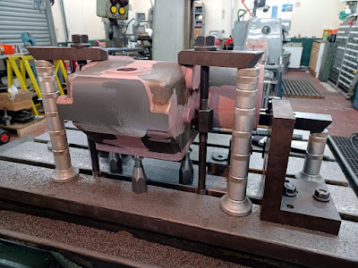
Mounted on a horizontal borer, the first operation was to mill the top face, which will ultimately carry the fuel pumps.     John Dunn Engineering


Another view, showing how the casting was mounted and clamped to the table   John Dunn Engineering


With the casting rotated through 90 degrees the end of the casing, which mounts onto the engine is shown here being faced off. John Dunn Engineering


Now it starts to get tricky! The shaft carrying the governor runs along the whole length of the casting. To ensure that it aligns perfectly the bores on both the left and right hand side of the box area need to be bored without re-setting the machine. Consequently the right hand bore have been machined with a boring bar projecting into the casting. John Dunn Engineering


An ingenious boring bar set up to allow the internal faces of the casting to be machined. John Dunn Engineering


The rather long reamer in the photo above is required to finish the bearings for the spindle of the governor operator bell crank lever. This is the sub-assembly 619 – 622 in the spare parts diagram included in the blog entry of the 10th February 2020. The photo below shows the same area on the MBD2 engine and tries to illustrate and explain how this part of the mechanism works. The lever is on the end of the shaft and is part 620, the fuel reducing claw lever (the kill switch for the engine).


The arm of part 621, the governor operating bell crank lever (which is carried on the same shaft) can be seen (with the low ball joint) inside the casting. The crank arm passes from one cavity of the body to the other via the hole in the top RH corner of the photo with the boring bar. The casting is upside down in the boring bar photo.


This view shows the machined top face of the casting, ready to receive the fuel pump assemblies. John Dunn Engineering


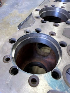
The interior of the machined casting. This end of the body receives the drive from the engine and contains the governor weights.


Even machining up the face of end cover was not a straightforward task, seen here on a vertical milling machine fitted with a rotary table.


Job done! John Dunn stands here with the finished item and the deserved look of pride that is usually associated with big game hunters. It seems rather underwhelming to record just another component has been finished.

Tuesday, 16 April 2024

Pump it up


While the amount of work still required on both the locomotive and the main engine shell should not be underestimated, much of what we need to do on both aspects of the project is graft. The fuel pump and governor assembly is the last big challenge as it is a complex box of tricks and while we have made good progress with the box (casting complete, as blog entry 19 January 2023), there are a lot of components to go inside it; 90 according to the McLaren spares catalogue (see blog entry for 10 February 2020).

The governor/ fuel pump assembly is highlighted in red, with the fuel pumps themselves being the four small cylinders, mounted on top of the box, with the pipes running off to the cylinder heads.

The casting for the body is currently with John Dunn Engineering for machining.

The blog entry for 16 February 2023 described the progress made in producing new injectors. To function the injectors need fuel pumps. Unlike the injectors we have not been able to source any drawings and there has been a lot of patient backroom work going on to clone these high spec, close tolerance units from the samples borrowed from the MDB2 engine.

The role of the pumps is to deliver a measured amount of fuel to the injectors, at a pressure which is sufficiently high to be injected into the cylinder at the top of its compression stroke. In the case of the MBD4, the fuel is injected at 1,000 psi.

The work carried out by Grange Square Engineering on the injectors was impressive, in terms of price, quality and timescale and we had no hesitation in asking them to quote for the fuel pumps too. As you will have probably gathered from previous reports, finding suppliers who are interested in manufacturing small batches of intricate components can be challenging. The relief in placing an order with a Company, knowing that they will do what you want in a realistic timescale was enormous.

The extract below is from a spares catalogue for MDB2 engines. The columns are ‘Part Number’, ‘6’ is the illustration number (the relevant part of which is reproduced) with the final column being the number off required (for a two-cylinder engine).


Only eight bits, but they do need to be right, exactly right if there are to do the job. The original pump bodies (part No 595) were forgings. While we are particular about how things are made, four forgings is never going to happen and Grange Square have CNC machined these from solid. It looks like there must have been a lot of swarf produced relative to the component size.

Machining the body for one of the fuel pumps (McLaren spares number 595) (image courtesy of Grange Square Engineering)

Replica fuel pump (left) with original fuel pump (right) borrowed from the MDB2 engine.


Another challenging component is the rack which lifts the cam followers which drive the pumps. The arrangement of this rack is different in concept of the MDB2 engine which is our primary source of reference to the one fitted to the MDB4 engine in the Armley Mills winch. We’ve taken our lead from the MDB4 engine. Grange Square has manufactured the new rack from the solid rather than the original forging. It may be politically incorrect to say ‘can you see what it is yet?' But you may need to look at the final illustration to understand the machining process shown in the three photos below.

The end of the rack appearing out the block (Grange Square Engineering)

Radiusing the arm corners (Grange Square Engineering)


A lot of swarf later and things are shaping up (Grange Square Engineering)

The finished product. 

So, nine bits done, 81 bits to go!

Monday, 15 April 2024

MDB4 Progress


You have to do a lot of scrolling back to find the last progress report on the McLaren-Benz MDB4 engine, 3 September 2021. This described the decision to dispatch the engine to a specialist restorer of vintage IC engines, Formhalls, to have the bearings re-metalled & the cylinder liners fitted. They are based a Salisbury, which is close to Stonehenge and consequently time moves at a different speed in Wiltshire. Their six weeks of Wiltshire time is two & half years of Gwynedd time. Ironically, when they heard we had had a crankshaft made by Farndons, they had the gall to mock their lack of communication & delivery skills. Mr Pot, meet Mrs Kettle!

Enough bitching, on the 13th March the engine arrived back at Boston Lodge, new crankcase bearings, whitemettalled & bore, big ends re-metalled, and cylinder liners fitted. Credit where it is due, there also find all sorts of little cracks radiating from the cylinder head studs & these have been laser welded up.


Line boring the crankshaft (image courtesy of Farndon Engineering)


The completed crankcase and bearings (image courtesy of Farndon Engineering)


A very sexy row of crankshafts (image courtesy of Farndon Engineering)


Laser welded repairs to cylinder head (image courtesy of Farndon Engineering)


Cylindrical grinding of cylinder liners prior to fitting (image courtesy of Farndon Engineering)


Cylinder liners ready to fit (image courtesy of Farndon Engineering)

Fortunately the return of the engine coincided with a period of leave for Rick, who duly got carried away. Job number one was to remove the plugs giving access to the oil ways. How the lubrication system works was described in the blog entry for 5 March 2018.

The illustration above is diagrammatic; the ‘pipes’ which lead to the crank shaft bearings are, in practice formed of a series of interconnected oilways drilled into the crank case and engine block. There is an oil way from one end of the block to the other, with individual branches leading to each crank shaft bearing location. At the end of each run there is a plug. When you remove the plugs and poke a small bottle brush in this is what you get out:

The cylinder heads had been overhauled earlier in the project (blog 10 April 2021) and in a moment of wild excitement one was trial fitted onto the cylinder block, with one of the MDB2 rocker covers. The rocker cover castings are still in Chris Barrys’ workshop. Wife, Kids, Dog, 7.5” rebuilds, pah! Come on Rimmer pull your finger out.


A frenzy of painting has ensured, so the cylinder block now looks like this, complete with replica McLaren-Benz plate.


It is not just the block that has been painted, the cylinder heads look lovely too


As do the myriad of cover plates etc. Even the MDB2 rocker covers have had a look-in


Next on the agenda is gasket manufacture. One down,


Some way still to go!

Monday, 10 July 2023

A Trip Across the Cob

 It would be churlish not to note 4415's trips from Boston Lodge across the Cob as part of the WHR100 celebrations on the 24th & 25th June as progress. 

All of Rob Collins’ lovely paint job will be getting grit blasted off in the next twelve months if we stick to the current plan to rivet up the body next winter, so here are a few views at least to capture some of the many completed components enjoying a trip out rather than languishing in the finished parts store. 

Seen below, meeting up with former Dinas shed mate ‘Russell’ at Boston Lodge at 08:54 on Saturday morning.


Optimistically coupled to a rake of 1920s style coaches below, it looks the part, and is the only decent photo I have showing the radiator & the replica ‘MACLAREN’ plate (cast using an original plate from the road roller).


In the end it ‘double headed’ with Welsh Pony, being somewhat lacking in the engine department.


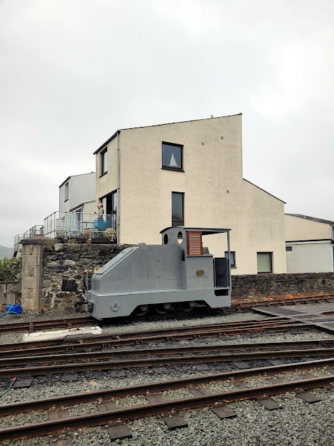
In addition to allegedly inspiring the streamlining on the A4s, the iconic look of KS4415 may have inspired the architect of Snowdon Wharf.


Eventually the sun came out, just as the loco returned to Boston Lodge on Saturday evening and a posed for a few minutes by the cliff.


Sunday saw 4415 going off shed with the full line up of surviving of Ffestiniog Railway early IC motive power.


The head turning impact of early IC motive power can be fully appreciated when you see the platform in this view of the 1917 build, 40HP petrol powered Motor Rail Tractor and the 1927 build 60HP Diesel 4415. It’s a niche market.


Some of the ‘facts’ in this blog may be made up.

Saturday, 10 June 2023

Engine Fitted To 4415!

Come on down and see for yourselves!  All of this frantic work on the body is of course to enable KS4415 to make a public appearance in Porthmadog during the Welsh Highland Railway 100 event on the 23rd-25th June. Who would have thought that the engine would be fitted before the event? Martin Greenland, Blackburne donkey engine restorer par excellence, that’s who.


A number of the completed components are going on to give a taste of the engineering as well as the appearance of the locomotive. No surprise that the MDB4 is still at Farndon Engineering. The above view shows the cab interior, partially fitted out with the petrol starting engine, starting gear box and radiator. There is a similar view in 15/- Change (which we can flog you out of the back of the cab if you have not already got one).
Now you can play ‘spot the difference’ and complain about the recess on the flywheel and the missing Diesel engine, the front hatch cover is removed in the old view,  no cab handrails in the new…

Ha! Cab handrails now planished (drawing 33362 refers). The one on the right is the replica, turned up by Rob Bishop and all of them have  been planished to within an inch of its life by Rob Collins. They are upside down in the photograph.

This view shows the handrails fitted, together with the cab back and driver seat (both original components).

We have had to let some new steel into the cab back, the majority (coloured red oxide) is original. The angle iron stay stiffens up the back sheet to ensure that overweight drivers do not buckle the sheet, another largely original component with a repair to the top. All of the other angle components are new.


To give the front elevation a bit more character the hatch handles have been recovered from the old hatch and fitted to the replacement.


So, looking more complete than it has done in many a year, 23rd-25th June will see this marvellous Diesel pioneer out and about. Come on over, see the beast, buy the merch!

Thursday, 8 June 2023

Making a spectacle

Like a moth to a flame I’m drawn to the awful and predictable pun, even though the Kerr Stuart drawing refers to them as a windows. Going back in time to the 17 October 21 blog, the mechanics of the window catches were described when Bob Smith and Adam Livingston were busy making the patterns, the castings from which arrived back in time to make an appearance in the 16 February 22 entry. Norman Bond has subsequently produced the patterns for both the round and rectangular windows and the components for these have been cast too, arriving during the special Christmas of 2022 with the injectors, governor body and a box of new drills to make all those rivet holes.

Our machinist man for these little jobs, Dave Linton (who is also our little man for machining jobs) has put some considerable mental effort into working out how best to set up the various bits for machining. This is the clamp set-up used in the four jaw chuck of the lathe to turn the catches and hinges.


The hinge castings and bearings are seen here post machining. The castings with the slots are the lower hinges to the windows.


The slots allow the hinge to clamp onto the pins, to hold the window in the open position.  The full assembly is shown here, with the wing nuts also machined by Dave.


Who also made all of the other brass components required to fit the hinges to the cab sides. 


Like all blokes who have kept something in their shed for years, he was particularly pleased that the kitchen worktop offcut from 1999 made a wonderful mounting plate to support the round windows for machining.  It is seen here mounted on a rotary table, being used to machine  two castings to make them into a matching pair. 


The drilling in the lower picture came first but it is hard to envisage the ingenious rotary table set-up from the drilling view. Worth capturing the moment in case you want to try this at home.


With all four castings drilled and mounted on the board Dave then put the whole set in in one of the Dean Smith & Grace lathes at Boston Lodge to skim them.


The various components, with the exception of the catches to hold the windows shut, are seen here in a dry-run assembly on the loco. It is curious that the bosses are outside the cab, requiring a slot cutting in the cab front.


Mounting the windows in this way moves the centre of the hinge pins outwards, allowing the hinges to be almost flush with the cab sheet (as shown in the drawing below). 


Another minor detail that is so nice to get right, which can be seen in the photo below: