Thursday 26 January 2017

A Removable Panel

Drawing, by Kerr Stuart, Photos by Emily High and Rob Bishop

We have, at long last reached the end of the frame repairs. At some stage in the past a section of the front, drivers side frame was made removable, possibly by Hunslets before the loco went to Mauritius. The Kerr Stuart frame drawing has a note ‘see HECo’s (Hunslet Engineering Co) drg No 30931 for alts to frames of L4415’. We don’t have a copy of that drawing, but the frames do not appear to have received any other modifications. The removable panel can be seen in the photo below, with the lay shaft bearing central in the panel. 


When you see what is behind the panel, the benefits of making it removable can be appreciated.


The photograph above is taken looking down into the frames from the front buffer beam, driver's side and shows the components located on the layshaft. From left to right can be seen the gear box, the front longitudinal frame stretcher, the spur gears taking the drive from the gear box to the lay shaft, the lay shaft chain sprocket (note the chain shaped wear on the hole in the stretcher behind) and the transmission band brake. All of this is contained behind the removable frame, and given that the sleeve which contains the lay shaft extends for the full width of the loco, getting at these components without the removable panel must be a nightmare.

So, non-original it may be, but retention is the way forward.


This is the frame extension, with the holes being tidied up on the radial arm drill.


The holes have been modified to take plough bolts; these have a counter sunk head, 
but a square on the shank to stop them turning when they are being tightened.


The frames with the removable plate re-fitted


Before the frame was re-fitted an opportunity was taken to ream out the bracket 
for the transmission brake and fit a new pin. 
The chains did nibble a good bit out of the frames (top right)! 
It is interesting that the opening in the frames have been flame cut

Saturday 21 January 2017

The Vacuum Exhauster

Drawing by Kerr Stuart,  Photo by Rob Bishop

In February 1929 KS4415 was fitted with vacuum brakes to allow it to be used on the thrice weekly Dinas to Beddgelert winter service. While there are no photos of it working these trains, the vacuum pipe is very evident in the series of photos taken of the loco in Minffordd yard later in 1929. Fortunately Kerr Stuart produced a series of drawings detailing the modification. An exhauster was formed using a Blackburne 500cc engine ‘complete without timing gear and other external fittings’. The ‘other external fittings’ presumably being the carburettor and magneto.


A second drawing details the various valves and mounting brackets required to turn the ‘4HP SV Blackburne Engine’ into a vacuum exhauster. 

Isn’t eBay a wonderful thing! You can buy anything on line these days, even small single cylinder engines from manufacturers who ceased trading long ago. This a 4HP, 500cc Blackburne side valve engine:


It needs some attention, and a chain drive from the gear box. How effective it will be as a vacuum pump we will find out eventually, and whether it can really cut the mustard is in the lap of the gods. One of the challenges of exhausters driven off the engine is their (lack of) ability to create adequate vacuum on tick-over. That’s why when you see ‘Mary Ann’ on a passenger train it is revving its nuts off in the platform just to maintain 21” of vacuum. Once you get going the exhauster pulls 25” and will suck the world inside out. The Kerr Stuart arrangement is driven off the gear box. This means that when you drop the revs and dip the clutch the exhauster is not working at all. 
Having a stock of newspaper and leather bootlaces will be a must for the toolbox. For non-believers, that’s technical advice from the Reverend Awdry on how to remove leaks from train pipes .   

Sunday 1 January 2017

Brake work

Photos by Rob Bishop


Rick and Matty's two-man working party is forging on with the restoration of the brake gear. This is a ‘top down’ overhaul, starting with the brake handle.

Before restoration:


After restoration:


The cap to the stanchion itself was very corroded, so this has been replaced:


And the whole assembly has been painted:


Reaming out the arm on the brake weighbar shaft:


The handbrake column connects to the weighbar via a slotted link,  not strictly necessary on a loco which also has a handbrake, but an essential feature if you have a powered brake. The drawings confirm that the steam powered locos which used the same chassis were fitted with steam brakes.

The slotted link needed machining out to accommodate the larger pin required because hole in the weighbar shaft had worn oval, a defect rectified by the reaming:


The completed sub-assembly:


One of the bearings which carry the weighbar shaft being bored out:


The completed weighbar re-fitted to the frames: 
(As the frames have already been orientated for a loco working in the southern hemisphere the whole thing is upside down to northern eyes)


The drawing below has a local orientation showing progress and the inter-relationship between the various components - they are all situated below the cab floor.


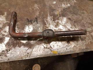
The leading brake pull rod has seen better days, but nothing that cannot be sorted out with gas and gentle persuasion:


For a job like this, it helps if you have three legs for some reason:


Some gas, a die nut and an amputation later: