Sunday 17 October 2021

Pattern Progress


Having described progress in the last blog on the bits of the engine we already have, this report captures progress on the missing bits. Our pattern making team of Bob Smith and Adam Livingston have had their work cut out.

It might feel like we are getting a bit ahead of ourselves, but firstly here are a few photos of the patterns produced for the spectacle hinges and catches, produced direct from the Kerr Stuart drawings. The somewhat wacky wing nuts are the catches for spectacles. The wings  are eccentric relative to the base. When you unscrew them it releases the spectacle allowing it to rotate.


The bottom hinge, cab38 is similar to the top hinge (cab52) and is formed from the same casting but the slit and wing nut assembly allows the spectacle to be locked in an open position. We are planning on getting these small brass parts cast in the near future to pass on to our home working machinists.


In addition to these brasswork ‘nice to haves’, patternmakers Bob & Adam have been working on the missing ironwork for the engine. 

This is the mould for the fuel filter, part number 852, together with its core boxes:

In this photo of the fuel filter patterns and core boxes, there is some patternmaker/foundryman black art going on. The two core boxes in the centre of the picture fit together so that the sand core can be formed inside them. This core will be used to create the void in the centre of the casting of the filter body. After the mould for the main filter body has been formed in the mould box (on the left), the core is added to occupy the stem area. 


The fuel filter is mounted on the end of the engine block to allow it to be heated by the water.  The void to the water space where the filter mounts is clearly visible on the final photo of the last  blog entry (3rd September 2021) .


Fuel for Diesel engines in the 1920s was not called ‘Diesel’ and to a certain extent they can run on ‘any old shit’, the McLaren running instructions includes some bio-fuel options and references ‘the heater arrangement’ (mounting the filter on the block) to reduce the viscosity of the fuel of choice.


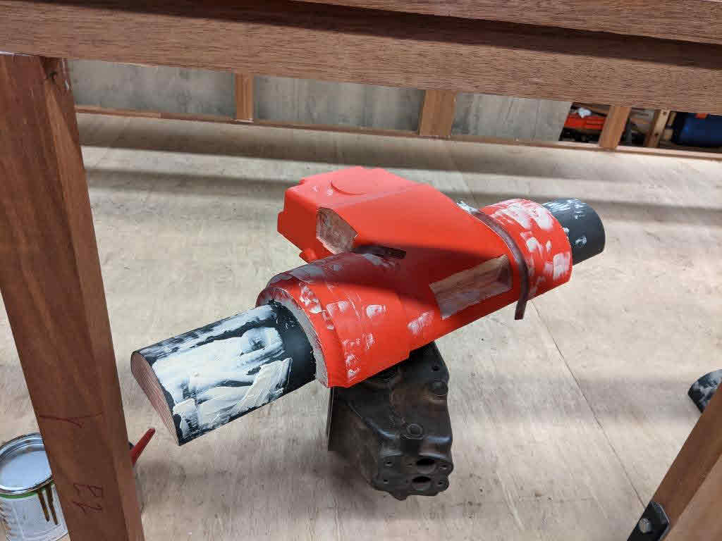
The really big pattern making job is the body for the fuel pump/governor assembly. Some of the drawings being prepared by Will High for this were included in the blog entry made on 16 February 2020. Here is another view of the beast:


This section provides some idea of the internal complexity of it:


Getting to the point of very precisely cutting wood for the pattern has been quite a journey.  The design is derived partly from the body of the MDB2 engine which we have dismantled so that it can reveal its secrets, and partly by taking measurements from the MDB4 engine owned by Armley Mills which we are seeking to replicate.

The MDB2 fuel pump body:


 The fuel pump on the Armley Mills winch:


Patternmaker Bob Smith is seen here with the fruits of his efforts, and those of the camera shy Adam Livingston:


The "balustrade" on the floor to the left of the bench is not going to grace some stately home, this is the main part of the pattern for the core which will form the central void in the casting: 

Imagine this big boy as a huge column of densely packed sand!


This is the pattern for the central portion of the fuel pump body which will house the cams and pushrods operating the pump units; the semi-circular components in the bottom of the photo will support the core.


To say that there has been quite a bit of effort put into creating this one component is something of an understatement, but getting it right from a conservation perspective is an important aspect to the project.


Friday 3 September 2021

MDB4 Progress

All of the stuff in the last blog was a bit of a distraction from the main task which needs to be progressed, that of getting the crankshaft bearings sorted so that the engine re-assembly can commence. Another key task is replacing the cylinder liners. One of these had been removed some time ago and this has been used as a sample to order some replacements.

The old liners were very secure in the block, and only after Mike's Dad's big hydraulic puller had turned up did they finally succumb with a "pop". The look of apprehension on Chris ‘Rimmer’ Barry’s face says it all:


A view down the water way of the empty block is akin to looking down the nave of a Norman cathedral. (The water pump mounts on to the stubs in the foreground):


This lovely cardboard box contains the replacement studs to re-assemble the block/crankcase, and also to fit the bearings. They have a metric fine thread; the engine is British made but metric, reflecting its German heritage:


Earle & Ed Ford cleaning out the threads before a trial fit of the studs:


With the stubs re-fitted the block was briefly re-mounted on the crank case, giving a false impression that progress is being made:


Just to add to all the "fur coat and no knickers" progress being made on engine re-assembly, a shot from Rimmers workshop in Manchester of machining up one of the new rocker covers (or ‘cylinder head dust covers’ to use the McLaren parlance): 

After some debate with the Boston Lodge staff, a decision has been taken that getting the crankshaft bearings white-metalled and re-bored to Diesel engine tolerances would be better arranged as an outside contract. So the big bits of the engine have been palleted up and dispatched to Formhalls, a specialist vintage & racing engine restorer, who has also been tasked with fitting the liners and re-metalling the big ends.  Crank case and pistons are on this pallet:


Crankshaft, engine block and cylinder liners are on this one. The studs and bearings are in there too somewhere:


If you’re thinking, wow, when that comes back all the big bits will be together, don’t! 

There is quite a bit of cleaning up to do when it returns, particularly of all of the oilway runs. But significant re-assembly is approaching.


Tuesday 15 June 2021

A New Start

The last blog entry closed with advice from McLaren regarding starting the engine from a Diesel perspective; crank away and the engine will fire’. The first working party of 2021 saw a new base established for the engine restoration in the recently restored Blacksmiths Shop at Boston Lodge. The Blacksmiths Shop project is not complete, so there is an element of camping out but has the big advantage of being a space that does not need to be vacated after a working party which will save a lot of time.

Racking has been set up to store both finished and unrestored items and the frame initially fabricated to hold the MR4 engine has been set up to provide a base onto which the MDB4 will be rebuilt.

Martin Greenland had a concern that the Blackburne engine may run ‘the wrong way’ relative to the Diesel and this led into an investigation of the starting gear arrangement. We have been very fortunate that the McLaren engine from Armley Mills arrived with a kit of parts to assemble the starting gear and it is apparent from the various holes in the frames and glimpses of the cab interior in photographs that the starting arrangement is of McLaren and not Kerr Stuart design and manufacture.

In a moment of keenness a couple of bits of angle have been welded to the temporary engine frame to allow the starting gear to be erected.


Like many mechanisms it is simultaneously simple and complicated, so don’t start reading this unless you are fully committed or desperately need to get to sleep. The view below shows the upper shaft of the starting gear. The pulley on the left is attached to the crankshaft and drives the water pump and fan. Between it and the gearwheel is a ‘claw clutch’ (as McLaren call it). The claw clutch is engaged/ disengaged by the horizontal lever in the upper photograph.

The view below is of the claw clutch. When the claw clutch is engaged it is possible to turn over the Diesel engine by hand by placing a handle on the square on the outer end of the shaft. If (or should that be when) the Diesel engine fires up it will rotate faster than poor sap turning the handle and over-ride the clutch which can then be disengaged.

 The lower bearing in the mechanism carries a shaft which is powered by the petrol engine and which drives the Diesel engine via the gearwheel. This view of the Armley Mills restored winch is from a similar viewpoint on the opposite side. The chain drive from the petrol donkey engine can be seen on the RHS in this view.

This view of the radiator end of the Armley Mills winch shows the lower shaft mechanism, chain driven in this instance by a twin-cylinder, water cooled JAP engine (also fitted to some of the 60HP Diesels, but not 4415).

There’s a bit of work to sort out the friction clutch plate and the ‘small hand brake’, but we do have all of these components.


What a relief it must have been when starter motors and batteries had enough oomph in them to start a Diesel. Fortunately the McLaren Running Instructions tell you all you need to know about what you have to do & when, which is a little bit more than the present day equivalent; insert key and turn clockwise.


Saturday 10 April 2021

Cylinder Heads Returned

 It is a long time since the 18th July 2019, when the rather sad looking cylinder heads were being dispatched to T&L Engineering…


Now they’re back and in the words of Madonna look shiny and new:


The new cylinder liners are expected soon too, so we are starting to accumulate quite a number of large components ready for re-assembly. While all this is exciting, the focus now needs to move from the big bits to the small bits, of which there are many!


This diagram is an edited extract from the MDB Running Instructions book (cropped to show the heads only). Sorting out the tappet rods (M) which run through the two brass lined holes in the photo above, together with the associated Fork Holders (9) & Check Nuts (10) is now on the to-do list. The Rocker Levers (N) & the Rocker Lever Brackets (11) need some TLC and are marinating in a bucket of Diesel. Lacking Ricks’ efficiency at recording progress I forgot to take a photo of them. A Diesel bath will not fix them, but it will hopefully make them easier to dismantle.

After spending an afternoon rooting through bins of rusty bits that will one day live and breathe fire it looks like there will be a need to make some new Torch Holders (i). The running instructions provide guidance on the use of the torch holders when starting the two or three cylinder engines (which are started by hand) but make no reference to their use when  an auxiliary engine is used (as is the case with 4415). 

The elephant not in the room regarding all of this is of course the atomisers. We think we have sufficient knowledge & information to instruct the construction of these vital components. Some aspects of this project are challenging, ordering injectors to your own specification makes the instruction to make a new crankshaft feel quite mundane.

Tempting though it is to leave the guidance on the use of the Torch Holders hanging, the opportunity to restore the MDB2 and roll some roads still remains. That group of people needs to know that you have to:

    • Remove the Torch Holders, turn the engine 10 to 12 revolutions with the release screws on the atomisers (injectors) open (i.e. not injecting).

    • In cold weather injecting a small drop of paraffin through the torch holder fitting will assist starting

    • Close release screws on atomisers (now injecting fuel)

    • Place torch papers (cigarette paper) in holders, ignite them and screw them into the heads, being careful to put each holder back into the correct cylinder

    • Crank away with the compression relief lever open (to the left); when the engine is up to speed, move the compression lever to the middle (half compression) and the engine will fire (the instructions say)  


Thursday 18 February 2021

Blackburne Engine Complete

 The 13 November 2020 report described the progress Martin Greenland was making on rebuilding the Blackburne 4HP donkey engine. It’s good to report that we have a tick in the box for the donkey engine and the team is looking forward to the time that the spark meets the petrol.


There is no drawing of the engine mounting, but the starting engine drawing does provide guidance on the height
 and there is a detail for the cast iron mount.


As an aside the starting engine drawing also includes a detail for the sump drain from the MDB4. If anyone has a Winns medium pattern No1700 ½” gas screwed plug cock in their shed we’ll be very pleased to hear from you, this is not a project for compromises. Combining the words ‘screwed’, ‘plug’ and ‘cock’ in a Google search isn’t great and while I now know a little bit about Charles Winn & Co of Granville Street, Birmingham, my education has been increased in other ways too.


In the terms of the story of early Diesel traction having the petrol engine is an important part of the tale. Without irony 15/- Change states …’one of the greatest drawbacks of the ordinary petrol engine… is the difficulty of starting them in cold weather’ before also observing the starting a Diesel in cold weather is very difficult and that the solution is to fit a petrol engine to start the Diesel engine. If the ever optimistic brochure is correct then on a cold morning this little beauty will be spluttering away for 2 ½ to 3 minutes before the Diesel starts. This is the overture, preparing the audience for what is to come!


Wednesday 27 January 2021

MDB4 Progress January 2021

Winter is usually a good time for Kerr Stuart progress, with the distraction of train playing reduced.  After some tussles to find a bit of space at Boston Lodge, Rick cracks on and makes progress while other members of the team sit back and relax in the reflected glory of his progress. 

This winter is different from others, but with the steady drip, drip of stalagmite formation, progress continues to be made. In the 25/10/18 blog the dispatch of the crankshaft to Farndon Engineering was reported, closing with the line Imagine the excitement when the new one comes back and we start worrying about the broken piston, the missing fuel pump and injectors…  

Brace yourselves; it’s back. Obviously still fretting about the other bits on the list, but two of the biggest challenges facing the engine restoration have now been ticked off with the repair of both the crankcase and the crankshaft.


Before we formally accept the delivery of this significant component, we are hoping that one of the works machinists will be able to give it a dimensional check. Assuming that it is fine, then this will free up some work to be carried out by the staff at Boston Lodge. 

After a rummage round in the store of components, the crankshaft bearings and housings have been locatedfor a quick trial fit up to understand what we have, and what needs doing.


Hopefully the next job will remove the last of the crankshaft failure damage. The bearings need to be re-whitemetalled and then bored out to fit the new shaft. The rather nasty score marks in the photo below show the point of crankshaft failure. 


Moving from the bottom to the top of the engine, the 16/2/20 blog reported on the dispatch to the foundry of the rocker covers. These have now been cast and are with Chris ‘Rimmer’ Barry, who has offered to machine them up as a homework project.   


Still some way to go and clearly difficult to be bullish regarding progress, but we also have the cylinder heads away with T&L Engineering and also have new cylinder liners on order, so we are getting close to the point when we stop taking things apart, and start putting them back together.  

When that will be of course is anybody’s guess.