Friday 26 October 2018

Crankshaft

Images by Rob Bishop


OK you wait months for an update and then three come along at once. Back in March the jury was out on the best option to sort out the crankshaft. Clearly it is very dead. While there is no intention to bury it, the carriage works volunteers have made it a beautiful casket.


It has gone on to a better place, Farndon Engineering in Coventry, who have been commissioned to make a replacement. In round figure terms this will cost £8,000, which leaves the kitty looking very bare. The recent donation of £1,000 from the FR Bristol Area Group has been a big help to keep this aspect of the project running. Farndon didn’t have an ‘order now for Christmas’ offer on, but there is still quite a bit to do on the gearbox which requires labour and not too much cash, and there are plenty of other rusty bits to be going at.

A last look in the coffin to the crankshaft with its broken neck. Imagine the excitement when the new one comes back and we start worrying about the broken piston, the missing fuel pump and injectors…


Clutch Plate?


Images by Emily High & Rob Bishop


I do know what the definition of a clutch plate is, but what do you call a plate which carries a clutch? It is the latter that I am going to describe, which I hope is more interesting than it sounds. Let me take you, the reader back in time. The image below is of the loco during the dismantling process. The plate in question is that part of the frame between the engine and the gearbox. The more observant will notice that there is a cone clutch within the flywheel and therefore the pedants may argue that my ‘clutch plate’ does not support the clutch.


This extract from drawing 33338 is interesting in this context. 
There is a housing for a quite different (plate clutch) unit.

The plate clutch was not successful and was replaced with a cone clutch, new drawings being issued in January & February 1929. The plan view from the same drawing tells the story; it shows the footprint of the clutch housing with the words ‘4 bolts not required 4418’.
Do you like the call off for the holes to secure the plate to the frames? It reads ‘5/8” bolts, 5/8”+1/32” holes’. An interesting way to define the tolerance.

The 5/8” bolts had seen better days when the loco was stripped down, the little pimples in the photo below is all that remains of them.
As the plate is also heavily corroded a decision has been made to replace it.


The working party of Rob Bishop, Matty Wolstenholme and Tim O’Donnell did a lovely job of forming these pan head rivets.
It’s a pity no-one will see them.

The rivets secure the angle at the rear to the plate. The pan-heads are underneath. Obviously we won’t be fitting the plate clutch, but the bolt holes (in the centre) are there just in case. The replacement plate has only one hand hole (as shown on the original drawing). We have not managed to fathom out why the two additional holes were added to the old plate. Perhaps we will find out when we try to bolt stuff down.


One reason for not reproducing the additional hand holes is that the vacuum exhauster is mounted on the plate, so there are two more holes to add, to bolt down the cast iron base described in the August update.

Coupling Update

Images by Rob Bishop

Although the chopper couplings were fitted some time ago, some detail aspects were incomplete. The pending gearbox re-fit will make access to the front dragbox difficult and acted as a spur to completing the couplings. Back in September 2016 the resurrection of some old, split face chopper couplings was described. The distance between the old buffer face and the coupling eccentric cam is a non-standard dimension, meaning that when coupled, the chopper faces do not meet and there is a risk that the hook may disengage due to the slack. Not too great a problem when being shunted round Boston Lodge yard but a reportable incident when the train divides in section.

The solution has been to mill part of the old buffing face off and weld on a new face plate, 
bringing the buffing face to hook eccentric distance to a standard dimension.

The face of a coupling being milled off in the horizontal borer


New ‘fat face’ welded on to the cleaned up coupling


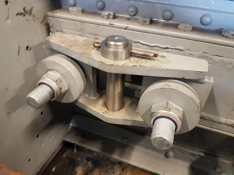
We’ve also had some cast iron bosses made to provide vertical support for the chopper coupling
 and have fitted some side chains to complete the early 1929 look. 
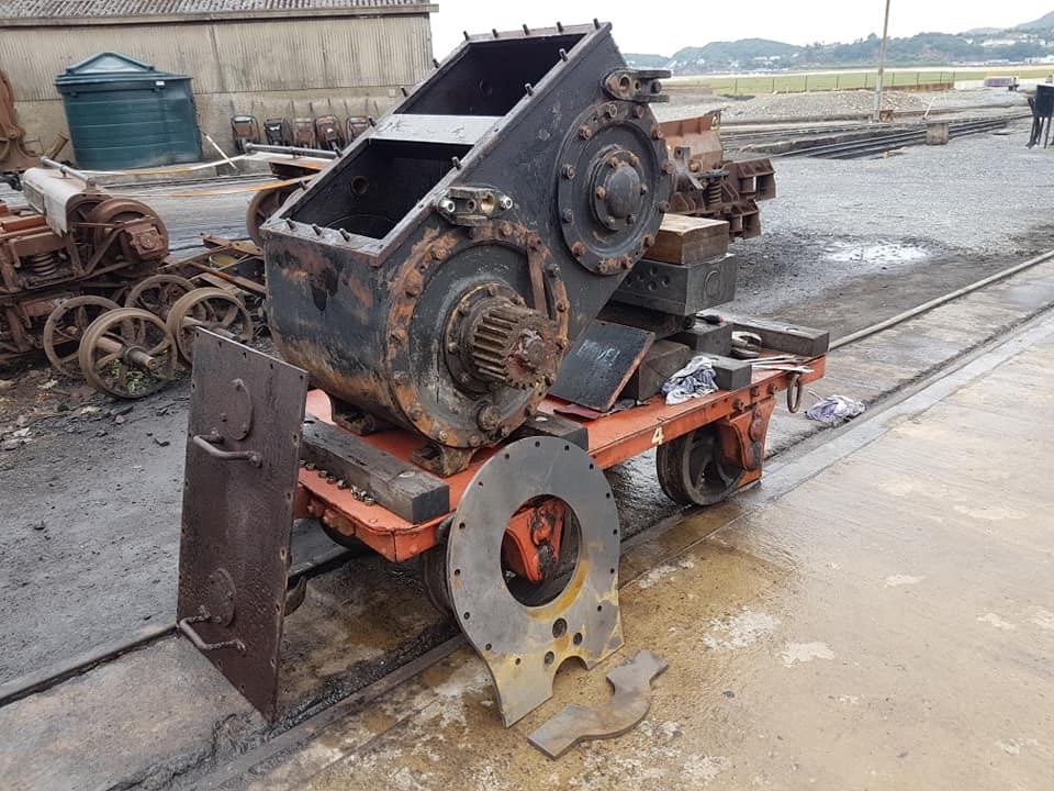

The Dragbox
While the boss castings are made to suit the modern dragbox arrangement (which has a lot of side swing), the detailing is taken from Kerr Stuart drawing 33736, ‘Arrangement of Vacuum Pipes For Diesel Loco 4415’. The new casting has a larger opening to suit the end swing of the coupling.


Behind the front buffer beam the coupling pivot on the dragbox needs the pin inserting from below as access from the top
 will be impossible once the gearbox is in situ. The options however are limited. Good to get this task finished now. 
Doubtless there will be new entries into the profanasaurus if that split pin ever needs taking out; 
"which ****** put this together - it’s as if they put this pin in and then built the whole machine around it!!"
  (They did and his name is Rob Bishop) 


After closing on paint drying for the last blog entry, this time we feature hole staring; the arc of holes in the plate to the left of the dragbox is for the bolts to fasten the external gear cover to the frame (see paint drying, 11/10/18). The cover will be on the other side of the plate illustrated.   


Thursday 18 October 2018

Gearbox update

KS4415 Update 11/10/18

Images by Rob Bishop

The blog entry December 2017 described a trial fitting of the gear box in the frames. The deliberations from that trial fitting led to the drawings in the 5th March 2018 entry which illustrated the proposed repair, using plates which bolt to the annulus around the bottom bearing housing.  The new components have been manufactured and are seen here with the cleaned up gear box.


The annular ring for the RHS plate is to allow it to be fitted outside the frame stretcher, as space in this part of the loco is at a premium.


If it all goes to plan it will assemble like this:


Before painting, the gearbox has been given a very thorough wire brushing; what a thing of beauty! Note the line of brazing on the rear face, bottom left.


This is a brazed repair to a crack in the casing; the crack is still visible on the inside.


Inside the gear box the drive from the (upper) forward/ reverse shaft to the lower (high/ low gear) shaft is via a chain drive (see below). If a link comes off the chain, the still rotating upper shaft brings all the chain up in the box and piles it onto the top shelf.  There isn’t enough space for this, the result is evident.


In the view below the gearbox is lying face down and the damaged lugs which support the gearbox on the layshaft can be seen, hence the new supporting plates. The next task is to replace the studs which fix the lower cover with some longer ones that are able to pick up the plates.


Progress on the new mounting plates is illustrated below. One pair of blocks which will secure the two halves of the mounting plate around the layshaft have been machined and drilled. The tack welds are temporary.


Finally, because we know that watching progress on the project is like watching paint dry, here is a picture of some paint drying. The green panel is the front cover to the gearbox, the grey components are the covers to the external gears (on the outside of the gearbox and on the layshaft). Some work to do before they are re-fitted!