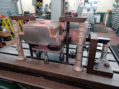
With the engine block back at Boston Lodge, job No 1 (or more precisely job No 2, after the painting epic) has been to fit the new liners. The manner in which the liners are fitted is a little unusual, as they are secured into the bottom of the block with an arrangement which is akin to a gland. The photo below shows the arrangement before dismantling. The liner clamp is secured by the four studs with the natty, shaped washers and there is a coil spring (in compression) between the washer and the clamp. Looking at the second picture, which shows the clamp being removed, may help understand the arrangement.
With the locked nuts, natty washers and springs removed the liner clamp can be lifted out.
The clamp both holds the liner in place and also compresses an ‘O’ ring, fitted around the liner to form a seal between the liner and the cylinder block water jacket.
The cylinders are off-set slightly from the line of the crankshaft (to ensure that the full force of the cylinder firing it put to good use) and to accommodate this each liner is slotted at the lower end to accommodate the movement of the piston rod. It goes without saying that ensuring the alignment of the liner is correct is critical. Rob Bishop fabricated this simple jig, which locates on the studs and then ensures that the slot in the liner is in the correct location.
With the liner in, the ‘O’ ring can be fitted, some sealant applied and the liner clamp re-fitted. Simples! The need for the jig can clearly be seen in the photo below where liner number 2 is clearly out of line.
One of the liner clamps had a crack;
So Rob fabricated a replacement. The old, cracked liner clamp on the left, new, fabricated replacement on the right.
The photo below, showing the new liner clamp being bored out on the lathe makes the welded construction more apparent.
Back on the engine, this view below shows the fitted liner and ‘O’ ring.
Things don’t always go to plan, the liner clamps are in compression, but the lugs are in shear and cast iron is the best material in shear. When the liner clamps were being fitted the lugs started breaking off. It looks like this one may have been cracked too.
The solution? We are going to get some new ones cast in ‘SG’ cast iron, which is more ductile than the normal stuff. Why didn’t McLaren use SG iron, you may ask? It was not invented until 1943, 15 years after the engine was built. In addition to the change in material the clamp has also had a modest size increase, to beef it up a bit. Thanks to Andy Williams for making a pattern for the replacement component so quickly.
As I expect the majority of people reading this will know, The Ravenglass & Eskdale Railway also had a Kerr Stuart Diesel (Standard Gauge, MDB6 powered) which if you didn’t know, takes a bit of taking in. Thanks, or possibly no thanks, to Neil Glover who forwarded an extract from a contemporary record (reproduced in the R&ER Magazine). It starts…
'we returned to Ravenglass a few days later after a pleasant holiday and discovered that the MacBenz engine had been in trouble.The water joints on the cylinder head and the liner joints had been leaking water into the sump’. After a vivid description of the rather unpleasant task of sorting the mess out it goes on to say ‘the job of renewing the joints was always with us, probably caused by vibration of the engine and also to some extent by a shortage of oil, causing the pistons to get hot. We always had a good stock of rubber joints to replace the faulty ones and as oil often stood on the cylinder heads from the tappets, the rings to seal the water often became impregnated with oil and were made useless’.
Maybe we are about to find out why liners were not often fitted like that. Let’s hope that improvements in rubber & sealants may give us a little bit of latitude.


