Wednesday, 24 May 2023

Body Talk


Much of the progress over the last five months has been boring. Literally. Probably used the joke before but I don’t care as the task of drilling the holes to allow the body to be assembled is nearing an end. Forming the lovely, new rectangular components was something that Boston Lodge is well set up for, as it has a large guillotine. Many of the sheet steel components are connected by rolled steel angles and while we have been able to recover one (as described in the 14th January 2023 blog entry) the others are too far wasted for re-use. Several of these angles are rolled to some quite tight radii, and require some skill to form them. In addition the main body wrapper, with its distinct ‘air-smoothed’ appearance is too corroded for re-use.

With the arrival of the wrapper, from Richards Sheet Metal the body started to move from being a series of one-dimensional components into something more tangible.


The recovered angle which connects the wrapper to the right hand side panel was soon trial fitted to find that the radii are beautiful match.


The other angle was too heavily corroded for re-use and a replacement has been manufactured by Chris Brady, a blacksmith from Tudweiliog.


Chris has also formed up a new angle hoop to connect the body to the cab, the very rusty remains of which were illustrated in the 14th January 2023 entry.


The body hatches (both top and front) are formed of two angle rings, one attached to the body, the other to the hatch which sit on top of each other. Chris has made these too and four more lovely pieces of angle iron you have never seen in your life.


The photo below shows the new, rear angle hoop and upper wrapper meeting the old side panel and angle. There is a rivet that attaches the angle to the side panel that needs to go in before the hoop is fitted.

After mucho drilling, the body is now a thing. The cut outs for the hatches have been partially laser cut, but left in situ to ensure that the body has some rigidity before the angle rings (which will add a lot of strength) are fitted.


The covers for the hatches have been ordered as laser cut parts. Here is Ben Boulter drilling even more holes to fasten the covers to the angle rings. The original front cover can also be seen in the photo, being used as a point of reference.


One of the cab side panels had some corrosion at the bottom. Chris ‘Rimmer’ Barry is seen here with the guillotine, about to remove a strip which has subsequently been replaced with new material.


A very tidy, massive rectangular hole had been cut into the other cab side at some stage in the past, so that has been replaced. The photo below shows the all new, right hand cab side, which is again full height for the first time since 1929.


Both cab and bonnet are rather large items to store in a workshop, so they have been temporarily mounted on the chassis. While we are quite pleased with the amount of original body that has been recovered (painted red oxide in the photo below) the amount of new steel added is all to apparent. In this view of the left hand side the new strip of steel grafted in to the lower can side can be noted.


The yellow blob on the cab side is a quick 'works plate'. There are two sets of holes, the outer holes are for the longer, elliptical Kerr, Stuart plates and the inner ones for the Hunslet/ Robert Hudson plates fitted in 1934.


Don’t buy a second hand car from Hunslets! In 1934 they were passing off second hand goods as new!


Dewi Atherton has machined up the replacement sliders for the shutters


This is the one good shutter slider that is fit for re-use attached to the replacement right hand side cab sheet


On the left hand side, the lower cab sheet is original but both shutter sliders are new. Seen here with a trial fitting of the teak shutters Clive Bickley produced in 2019 (see 11 December 2019 blog).


Rob Collins is seen here sanding back filler applied to tidy up some of the worst of the pitting to one of the old body panels.


With the front hatch temporarily fitted and a coat of primer Kerr, Stuart 4415 is quite an impressive beast.









Thursday, 16 February 2023

Injector Progress

Not content with getting all excited over the governor body casting, another significant milestone was been reached in the back burner department  in January. The injectors. The idea that we needed to source injectors from the dawn of time has always been somewhat daunting, given the precise nature of these components. 

Fortunately the Armley Mills archive did include a set of drawings for them, however these lacked some of the information we would have liked on materials and tolerances. The blog entry for 25th May 2019 illustrated the injectors borrowed from the MDB2 together with an illustration from the McLaren-Benz Catalogue which captures the complexity of these wee beasties, reproduced here too.


For understandable reasons, no-one from the world of 21st Century Diesels was going to make a little batch of injectors like this, however some contacts at Mercedes-Benz were very helpful with materials and tolerance advice. Paul Turner took the McLaren drawings and cadded them up. As these are Benz components being manufactured by McLaren the old drawings were already in metric which kept things nice and simple.
Eventually we found a company that are interested in manufacturing small batches of fiddly components, Grange Square Engineering. They turned our order for ten sets of bits round very quickly. 


Before and after, one of the new injectors together with a sample borrowed from the MDB2 engine.
It must be emphasised that despite appearances, these are a set of bits which require assembly by somebody who knows what they are doing to ensure that the fit and finish is right.


These are parts C and D, the needle valve body nut and the needle valve body. We have not got all the bits A to Q (no sprayer valve spring, part F for example) but is great to have money spent and a box full of bits. We don’t have to worry about making them, now the fear is getting them to work.
After getting all excited about that we are heads down and on with more drilling to prepare the cab sides for riveting.

Thursday, 19 January 2023

Cast in Sand

 Something that has been exercising our minds and the pattern makers arm muscles for some time is the fuel pump and governor unit. The blog entries for 10th& 16th February 2020 describe the inner workings of this unit and that of 17th October 2021 summarises progress on making the pattern for the governor housing and the fuel filter. 

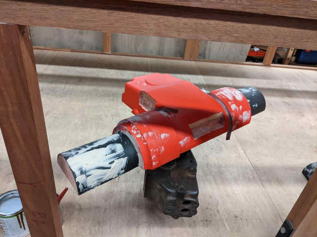
Both these patterns have now been completed by Bob Smith & Adam Livingston. Bob trained as a pattern maker straight out of school and is now retired. He described it as the most complex item he has ever worked on. The main pattern and some of the coreboxes are illustrated below, together with the body of the similar, but smaller casting from the MDB2 engine, which has been used as a point of reference.


Given the complexity of the beast Bob & Adam tried their hands as moulders, to ensure the cores can be removed from the core boxes and that the necessary clearances can be achieved to produce the wall thicknesses required. An interesting exercise, which also proved in part that their skills lie elsewhere; being a moulder is a skill in its own right.


The chaps at Cerdic Foundry in Chard fortunately have all the skills required to turn wood into sand and ultimately into iron and another of the big hurdles for the project has now been cleared. If you turn to p26 illustration 6 of your McLaren spare parts catalogue you will of course recognize components 532 (Fuel Pump Gearbox) and 540 (end cover for fuel pump gear box).
.


Those who may have mislaid this useful reference will find the illustration from the catalogue in the 10th February 2020 blog entry, which has a painful reminder of how many small and intricate parts now need to be manufactured.

One photo hardly does justice to the massive amount of work that has gone into recreating this extremely complex component so here are a couple more views to allow it to be appreciated.


The fuel filter body is small and relatively simple by comparison. If you have the KS4415 Panini stickers book this is part number 852. The pattern and role of this component was described in the 17th October 2021 blog. Rather less daunting to complete, it is another useful work in progress milestone that has been passed.


Saturday, 14 January 2023

Progress! Progress!


It may be eleven months since the last blog entry, but progress over the last couple of months, since the end of the train playing season, is extremely encouraging. Some of the ‘slow burner’ projects which have required research, draughting and in many cases pattern making suddenly have tangible progress with components being delivered from outside contractors. When this paid-for progress occurs concurrently with the steady grind of the volunteer group on restoration tasks the advances made since the end of the train playing season are significant. From a restoration perspective, the fact that we are working on some quite large part that is relatively simple may suggest that things are moving on less quickly than they feel, says the pessimist.

The elephant that is not in the room is the engine block, which is still with specialist contractor Formhalls, another contractor we have used with specialist skills and no concept of programme. Putting a positive spin on their lack of progress, instead of plodding on with a diligent, engineering-led one nut and bolt at a time restoration we have made the erratic decision to go for a ‘fur coat and no knickers’ approach to restoring the body ahead of the engine. Even more mad (and something we try to avoid) is the use of ‘a deadline’. You have no doubt read it somewhere else first, but our intention is for KS4415 to make a side show appearance at the WHR centenary event, to be staged on the 23rd- 25th June 2023.


The appearance of the grit blasted components is encouraging and we will be able to re-use a lot of original material:


One of the angles used to attach the body sides to the top wrapper was found to pretty good. Rob Bishop grafted on a short section of new steel to the foot and it is fit for re-use (see below)


The condition of the cab-end brace is not so good and it will require replacement:


The lower body panels also require replacement and the sheet of steel required to make these in one piece needed a special two-bogie delivery to the guillotine:.

In addition to the two, new lower body panels there is enough steel in this sheet to provide the components required to repair/ replace the cab sides (as required).


Although the steel  order was large, we did not order the required holes. Scott Todd-Howard is seen cracking on with a boring (so droll!) task. The original bodyside (painted red oxide) has been bolted to the restored angle section. The lap plates (on the inside of the body, which cannot be seen here) have also been bolted on and the new (bare metal) panel is being drilled with holes for the rivets. There is an angle along the bottom of the new sheet which attaches the body to the chassis. This was too wasted for recovery and has been replaced:


 This photo shows the completed bodyside, with a new door temporarily put in place (the original was removed long ago in Mauritius).  The new lower angle can be seen, together with the small patch replacement near the seam to the left hand original panel:


One of those curious things that you never notice until you get down and dirty with this stuff is that the upper body panel of the loco, when built was formed of a single sheet of steel. Why is there a very neat, riveted, vertical joint in it now? There is an angle stiffener just to the left of join, which can be seen in this photo at California works:

Both sides are now at a similar stage of (in)completion. The other (drivers side) panel requires the angle frame to be replaced. Some holes and the worst areas of waste have been replaced in this panel (touched up with grey primer on the photo below).


Wednesday, 16 February 2022

Any Old Iron?


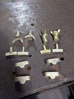
 Before we pick up on the main focus of recent work, the last blog entry illustrated the patterns for the spectacle hinges and catches. These are the castings, ready for machining.


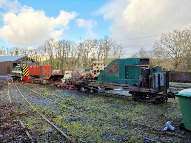
From a project perspective, the engine side of things has gone a bit south; to Salisbury to be precise and it yet to return. It is a little bit frustrating, but we’re not short of jobs. A trip to Minffordd saw this eclectic pile of tat extracted from the Maenofferen shed. After a sort-through, all of the material likely to be re-used was transferred to another wagon and taken to Boston Lodge.


Thirty minutes of fun to work out what is in this waggon and what we left behind

Obviously the big bit is the bonnet, enjoying a trip out ‘on the forks’ 


A pleasingly large amount of this is recoverable


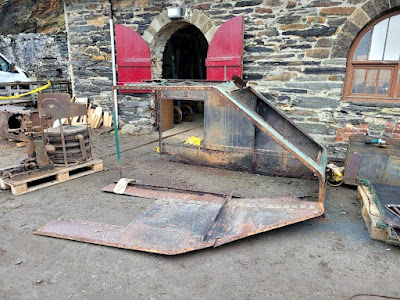
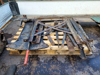
Not the easiest thing to store in the Blacksmiths shop, so Rick & Matty dismantled it into its component parts. This view shows the construction formed of angle frames and steel sheet, with a lap strip connecting the upper and lower body panels. This will make a nice break between the new and old construction when we rivet it all back together. 


It’s good to say that the flat packed body did not hang around in store for too long; it is seen here on the back of the Boston Lodge pick up at point of dispatch to the grit blasters in Nefyn.

In addition to the recoverable body panels the second pallet load includes the brake handle for the transmission brake, the clutch pedal and the frame to carry the fuel tank. The two sand pots have also gone for the grit blast treatment.

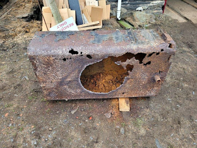
The fuel tank itself did not make the cut for restoration, for reasons that are all too obvious in this view. The fresh gas-cut hole is to aid recovery of the filler cap. 

The cast iron filler cap is quite a beast which we will of course be re-using.

Back to the tank itself, this displays some interesting remnants of it’s past. The two short angle brackets on the front face originally secured an auxiliary paraffin tank. Paraffin was used as a more combustible fuel to help start the engine. It you look carefully it can be seen that the right handle angle (in this view) fixed to the tank is marginally longer that its’ left hand mate. Historically this angle was longer still and carried a teak plinth on which the paraffin tank was mounted. Interestingly the fuel tank is a welded construction, which begs the question why did they rivet the angle brackets to it? 

This drawing extract shows the paraffin tank in detail. There are also front elevation and plan views.


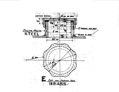
One of the joys of this project is of course the wealth of information available to inform the restoration. This is the detail for the filler cap to the paraffin tank. There is no mention of it being cast so Dave Linton has been dispatched with a suitable bit of brass bar to machine one up


Sunday, 17 October 2021

Pattern Progress


Having described progress in the last blog on the bits of the engine we already have, this report captures progress on the missing bits. Our pattern making team of Bob Smith and Adam Livingston have had their work cut out.

It might feel like we are getting a bit ahead of ourselves, but firstly here are a few photos of the patterns produced for the spectacle hinges and catches, produced direct from the Kerr Stuart drawings. The somewhat wacky wing nuts are the catches for spectacles. The wings  are eccentric relative to the base. When you unscrew them it releases the spectacle allowing it to rotate.


The bottom hinge, cab38 is similar to the top hinge (cab52) and is formed from the same casting but the slit and wing nut assembly allows the spectacle to be locked in an open position. We are planning on getting these small brass parts cast in the near future to pass on to our home working machinists.


In addition to these brasswork ‘nice to haves’, patternmakers Bob & Adam have been working on the missing ironwork for the engine. 

This is the mould for the fuel filter, part number 852, together with its core boxes:

In this photo of the fuel filter patterns and core boxes, there is some patternmaker/foundryman black art going on. The two core boxes in the centre of the picture fit together so that the sand core can be formed inside them. This core will be used to create the void in the centre of the casting of the filter body. After the mould for the main filter body has been formed in the mould box (on the left), the core is added to occupy the stem area. 


The fuel filter is mounted on the end of the engine block to allow it to be heated by the water.  The void to the water space where the filter mounts is clearly visible on the final photo of the last  blog entry (3rd September 2021) .


Fuel for Diesel engines in the 1920s was not called ‘Diesel’ and to a certain extent they can run on ‘any old shit’, the McLaren running instructions includes some bio-fuel options and references ‘the heater arrangement’ (mounting the filter on the block) to reduce the viscosity of the fuel of choice.


The really big pattern making job is the body for the fuel pump/governor assembly. Some of the drawings being prepared by Will High for this were included in the blog entry made on 16 February 2020. Here is another view of the beast:


This section provides some idea of the internal complexity of it:


Getting to the point of very precisely cutting wood for the pattern has been quite a journey.  The design is derived partly from the body of the MDB2 engine which we have dismantled so that it can reveal its secrets, and partly by taking measurements from the MDB4 engine owned by Armley Mills which we are seeking to replicate.

The MDB2 fuel pump body:


 The fuel pump on the Armley Mills winch:


Patternmaker Bob Smith is seen here with the fruits of his efforts, and those of the camera shy Adam Livingston:


The "balustrade" on the floor to the left of the bench is not going to grace some stately home, this is the main part of the pattern for the core which will form the central void in the casting: 

Imagine this big boy as a huge column of densely packed sand!


This is the pattern for the central portion of the fuel pump body which will house the cams and pushrods operating the pump units; the semi-circular components in the bottom of the photo will support the core.


To say that there has been quite a bit of effort put into creating this one component is something of an understatement, but getting it right from a conservation perspective is an important aspect to the project.