Images by
Emily High & Rob Bishop
This extract from drawing 33338 is interesting in this context.
There is a housing for a quite different (plate clutch) unit.
The plate clutch was not successful and was replaced with a cone clutch, new drawings being issued in January & February 1929. The plan view from the same drawing tells the story; it shows the footprint of the clutch housing with the words ‘4 bolts not required 4418’.
Do you like the call off for the holes to secure the plate to the frames? It reads ‘5/8” bolts, 5/8”+1/32” holes’. An interesting way to define the tolerance.
The 5/8” bolts had seen better days when the loco was stripped down, the little pimples in the photo below is all that remains of them.
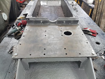
As the plate is also heavily corroded a decision has been made to replace it.
The working party of Rob Bishop, Matty Wolstenholme and Tim O’Donnell did a lovely job of forming these pan head rivets.
It’s a pity no-one will see them.
The rivets secure the angle at the rear to the plate. The pan-heads are underneath. Obviously we won’t be fitting the plate clutch, but the bolt holes (in the centre) are there just in case. The replacement plate has only one hand hole (as shown on the original drawing). We have not managed to fathom out why the two additional holes were added to the old plate. Perhaps we will find out when we try to bolt stuff down.
One reason for not reproducing the additional hand holes is that the vacuum exhauster is mounted on the plate, so there are two more holes to add, to bolt down the cast iron base described in the August update.


No comments:
Post a Comment